Fun With Pinball

Animated Single, Double and Triple Bonus Counts
Gottlieb's 1975 Quick Draw and Fast Draw pinball machines feature an end of ball bonus where a bonus accumulated during the current ball in play is counted down and added to the player's score when the ball drains. Based on the state of the game when the ball drains this bonus might be doubled or even tripled as it is counted down. Doubling the bonus count was common in games of this era, as demonstrated here for example, but tripling the bonus adds a layer of complication.
The Schematic Example
Here is a simplified version of the Quick Draw schematic showing how the bonus can be optionally doubled or tripled:
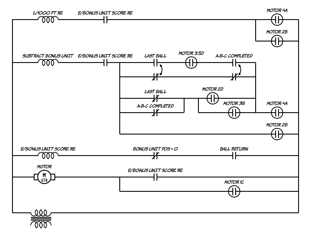
At the top of this schematic is the circuit for the L/1000 Point relay which advances the 1000 point score reel and fires the 1000 point chime when it is activated (although they're not shown here). Whenever the E/Bonus Unit Score relay is active, pulses from score motor switches 4A and 2B activate the L/1000 Point relay 6 times per score motor cycle. Another way to think of it is that as long as the bonus is being counted (or the Bonus Unit Score relay is active) 6000 points can be added to the score for each score motor cycle (1/3 turn or 120 degree rotation of the score motor).
Below the 1000 Point relay circuit is the circuit for the Subtract Bonus Unit solenoid which makes the Bonus Unit step unit step down one position each time the solenoid fires. During the game the Bonus Unit takes a step up for each 1000 point bonus achieved during the current ball in play. When the ball drains the bonus is counted down and points are awarded until the step unit reaches its zero position, indicating that all of the earned bonus has been awarded.
Notice that the Subtract Bonus Unit solenoid circuit includes switches on the E/Bonus Unit Score relay and Motor positions 4A and 2B just as the L/1000 Point relay circuit does. The extra switches in the middle of the circuit determine how often the Subtract Bonus Unit solenoid fires relative to the L/1000 Point relay. The ratio of how often these two devices fire determines how many points are awarded for each Bonus Unit step:
- Single or 1X bonus: 1000 Point relay fires once each time the Subtract Bonus Unit fires
- Double or 2X bonus: 1000 Point relay fires twice each time the Subtract Bonus Unit fires
- Triple or 3X bonus: 1000 Point relay fires three times each time the Subtract Bonus Unit fires
The circuit for the E/Bonus Unit Score relay near the bottom shows that the relay activates only when the Ball Return (or Out Hole) switch closes and there is some bonus to be counted, indicated by a switch that closes when the Bonus unit is not at zero.
The simplified Score Motor circuit at the bottom shows that the score motor only runs when there is a bonus to be counted, or to the next home or index position of the Score Motor, whichever comes last.
The Animated Circuit
Below is a simplified version of the circuits above that will be used in the circuit animations.
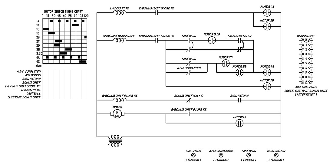 Animated Quick Draw Bonus circuit

On the left is the Motor Switch Timing chart. In the center are the circuits described above. On the right is a representation of the Bonus Unit showing its current position with the double arrow, and at the bottom are devices used to manipulate some of the switches in the circuit.
Single Bonus animation
On Quick Draw and Fast Draw a single bonus is counted at an unusual rate of 6000 points (or 6 pulses) per Score Motor cycle. The Score Motor sends 6 pulses per score motor cycle to the 1000 point relay and to Bonus Unit Subtract solenoid by combing pulses from the Motor 4A (5 pulses) and Motor 2B (1 pulse) switches. The Bonus unit takes a step down each time 1000 points is awarded as shown by the double arrow on the Bonus Unit moving down from a starting position of 8.
This single bonus animation starts with the Bonus Unit at position 8. The bonus unit counts down from 8 while the 1000 Point relay fires 8 times for a total of 8000 points.
Quick Draw Single Bonus circuit animation
In a single bonus scenario all 5 pulses from the Motor 4A switch get to the Subtract Bonus Unit solenoid through the two make/break switches in the second row of the circuit. The 6th pulse from the Motor 2B switch bypasses most of the complexity and is used to step the Bonus Unit down any time a bonus is counted.
The timing diagrams on the left show that each time the L/1000 Point relay coil fires the Subtract Bonus Unit solenoid also fires.
Note that the 2nd and 4th pulses from the Motor 4A switch also get through a parallel path via the Motor 2D and 3B switches (at 31 and 74 degrees into the score motor cycle). This is unnecessary and redundant in the single bonus case but will become important in the double bonus scenario.
Double Bonus animations
In the next animation the double bonus is enabled because the A, B and C rollover features have all been achieved. The two "A-B-C Completed" switches have toggled which changes the circuit for the Subtract Bonus Unit solenoid. The second row of the circuit that lets all 5 pulses from the Motor 4A switch through for a single bonus is now open so the 5 pulses can only try to get through via the Motor 2D and 3B switches. Looking at the Motor Switch Timing Chart the Motor 2D switch will only allow the 2nd of the Motor 4A pulses pass and the Motor 3B switch only allows the 4th Motor 4A pulse to pass. (More pulse masking examples are shown here.) The 6th pulse from the Motor 2B switch always gets through so of the 6 available pulses, only every other one gets through to step the Bonus Unit down. All 6 pulses always get to the 1000 Point relay so the 1000 point relay awards 6000 points per score motor cycle while the Bonus Unit steps down only 3 steps.
In this double bonus animation the Bonus Unit starts at position 4 and steps down to zero. The 1000 Point relay fires twice for each Bonus Unit step for a total award of 8000 points.
Quick Draw Double Bonus animation
The net effect of every other pulse getting through to the Subtract Bonus Unit solenoid is that 2000 points are awarded at each Bonus Unit step rather than just 1000 points so the bonus count is doubled.
A double bonus is also awarded on the last ball of the game. In this scenario it's not the two "A-B-C Completed" switches that have toggled, but the two "Last Ball" switches that have toggled. The changes to the circuit are essentially the same with 3 of the 6 available pulses per score motor cycle reaching the Subtract Bonus Unit solenoid.
Quick Draw Double Bonus on Last Ball
Triple Bonus animation
On Quick Draw and Fast Draw the bonus is tripled on the last ball if the A-B-C is also completed. In this scenario one pulse per score motor cycle gets through the top row of the circuit via the Motor 3.5D switch and a second pulse gets through the last row from the Motor 2B switch.
In this animation the Bonus Unit starts at position 3 and steps down to zero. For each Bonus Unit step the 1000 Point relay fires three times for a total award of 9000 points.
Quick Draw Triple Bonus animation
Only the first and last rows of the Subtract Bonus Unit circuit are used in the triple bonus scenario with each row allowing just one pulse to get through. The two middle rows block any pulses from getting through.
Circuit Summary
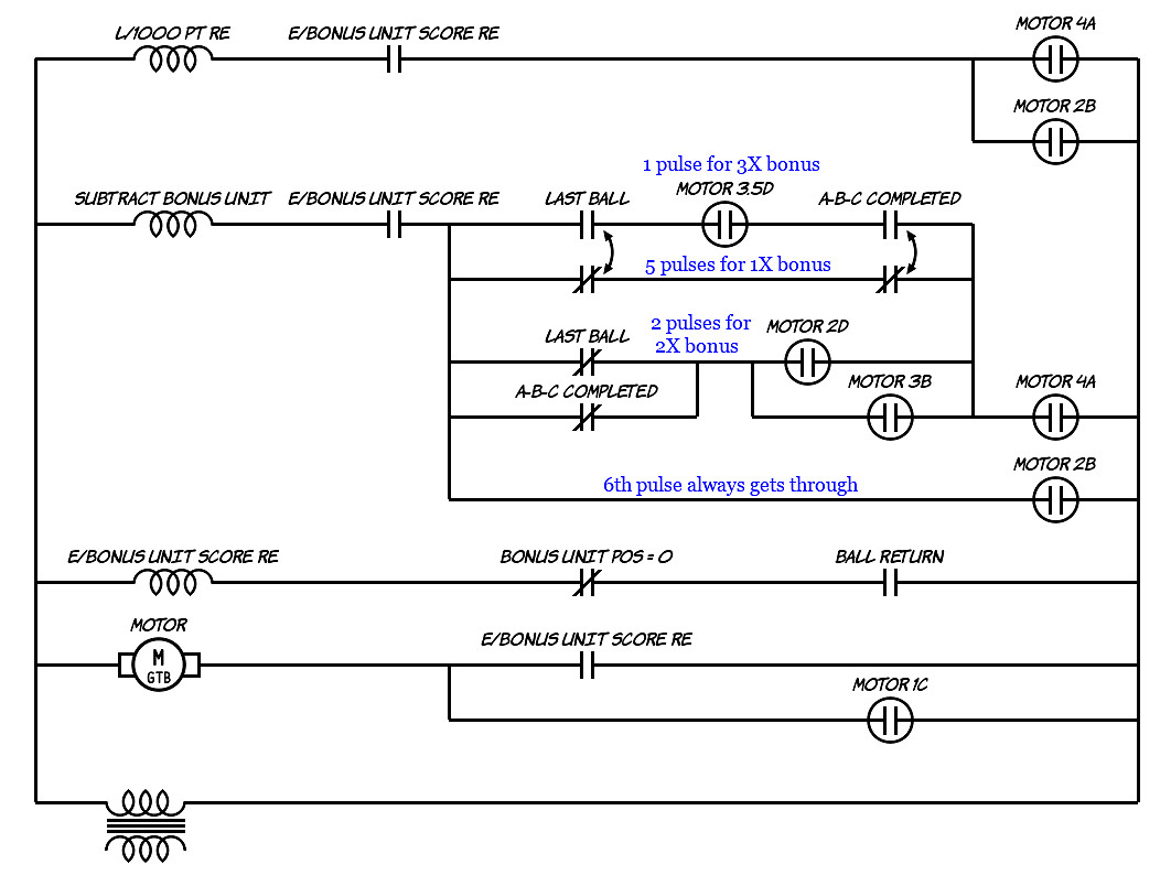
To summarize how the three different bonus multipliers work it all boils down to how often the Bonus Unit steps down relative to how often the 1000 Point relay fires. The annotated circuit below shows which circuits are used for which bonus multiplier:
 Quick Draw Bonus circuit summary
- All bonus counts get the 6th pulse from the Motor 2B switch through the last row of the Subtract Bonus Unit circuit.
- The top row of the circuit through the Motor 3.5D switch is used only for the 3X or triple bonus multiplier. It allows just the 3rd of the five Motor 4A switches through. Combined with the pulse from the Motor 2B switch the Bonus Unit takes two steps while the 1000 Point relay fires 6 times.
- The 2nd row through the two make/break switches is used only by the 1X or single bonus. It allows all five Motor 4A pulses through which combined with the 6th pulse from the Motor 2B switch makes the Bonus Unit step down each time the 1000 Point relay fires.
- The 3rd row through the Motor 2D and 3B switches, used by the 2X or double bonus, allows just two pulses through so the Bonus Unit steps three times in a score motor cycle while the 1000 Point relay fires six times.
A Schematic Error?
The circuit behavior presented here assumes that the Motor 3 1/2 D (or 3.5D) pulse overlaps the 3rd Motor 4A pulse. If you compare the Sequence Charts used here with the Sequence Chart used on the original schematic there is a discrepancy:
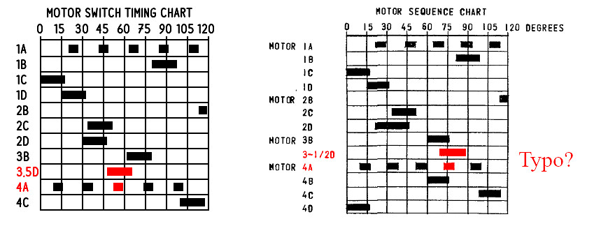 Quick Draw Sequence Chart Discrepancy
The original schematic on the right shows the Motor 3 1/2 D pulse overlapping the 4th Motor 4A pulse. If this were the case the Bonus Unit would step on the 4th and 6th Motor 4A pulses rather than the 3rd and 6th pulses. That would result in 4000 points being awarded for one step and 2000 points being awarded for the subsequent step in a triple bonus scenario. The total awarded points would not be correct if the Bonus Unit started at an odd position. For example a triple bonus starting at position 3 would award 4000 + 2000 + 4000 or 10,000 points instead of 9000 points (3 x 3000).
Animated Schematic Diagrams
Follow these links to other animated schematic diagrams:
>
>
>
>
>
>
>
>
>
>
>
>
Basic circuits
Score Motor circuits for Scoring
Score Motor circuit for Ball Return
Step Unit circuits
Score Reel Reset circuit
1975 Gottlieb Atlantis Dual Drop Target Scoring circuit
Gottlieb Player Unit circuit
Bally & Williams 4 Player Ball Count circuit
1972 Gottlieb Grand Slam Base Runner Tracking
Single and Double Bonus Count
Single, Double & Triple Bonus Count
2 Coins Per Play
Gottlieb Score Motor Pulse Masking