Fun With Pinball

Repairing a Bally Motorized Trip Relay Bank
Starting with Rocket III in 1967 Bally introduced a new device in some of its pinball machines called the Motorized Trip Relay bank. Trip relay banks (as seen in the Puzzle) had been commonly used in pinball machines for decades. Trip relays, grouped in banks of a few to nearly two dozen, behave like circuit breakers. Once they are activated or tripped, they remain tripped until they are mechanically reset by a common reset arm driven by a large solenoid or two. Trip relays have an advantage over simple relays of being able to remember state indefinitely without consuming any power. They're often used for example to keep track of which targets have been hit when an award is based on how many targets have been hit.
Bally's Motorized Trip Relay banks behave like other trip relay banks except that the reset mechanism is very different. Instead of a common reset bar that resets all of the relays simultaneously, these banks use a rotating shaft driven by a motor. Plastic cams mounted to the rotating shaft reset each relay armature, one at a time.
The problem with Motorized Trip Relays is that they were only used in a few games in the late 1960s and early 1970s so most of the parts are no longer available.
1969 Ball On Beam
While restoring a 1969 Bally On Beam I discovered a problem with its Motorized Trip Relay bank. The last few relays in the bank would not reset. Upon closer inspection I found that several of the reset cams were damaged as shown in this video:
Incomplete reset with damaged cams
The rotating reset cams are driven from one end (by the two red clutches in this game). Each reset cam has a notch on one end and a matching tooth on the other end so that each cam interlocks with, and drives its neighbor. The problem here is that some of the cam notch edges had chipped away and enlarged the notch so the cam did not engage fully with its neighbor or rotate it completely. Each damaged cam reduces how much the rest of the cams rotate. With three damaged cams in the bank the last two cams don't rotate far enough to reset their relay armatures.
 Damaged reset cams
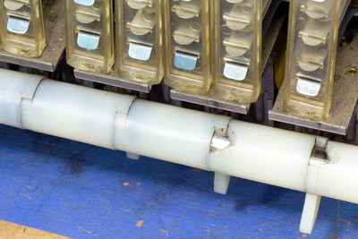 Damaged reset cams
The damaged reset cams need to be replaced to resolve the problem.
New Reset Cams
Parts for the reset mechanism of the Motorized Trip Relays are no longer available so replacements had to be made. I had a couple of NOS reset cams (Bally part C-706) but not enough to replace all three cams. I wanted to try to recreate the cams anyway so I started by scanning the business end of an NOS cam. Then I imported the scan into FreeCAD and cobbled together a CAD model of the damaged parts:
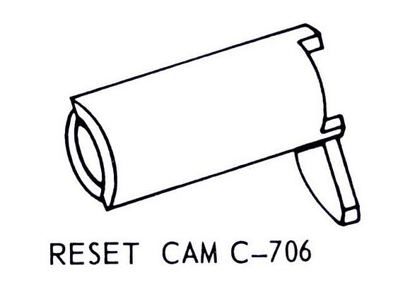 Bally Reset Cam C-706
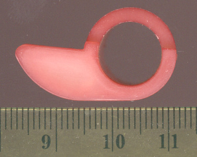 Scan of NOS reset cam
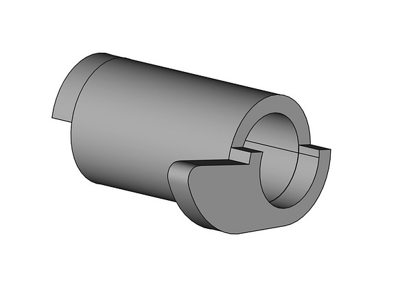
It turned out that the NOS part I measured to create the CAD model was slightly shorter than the cams in the game so I had to revise the model to make it a little longer. The NOS, damaged and replacement cams are shown below for comparison.
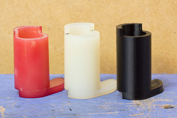 NOS, damaged, and replacement cams
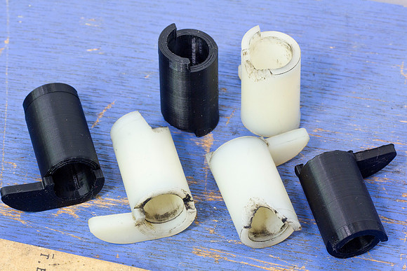 Damaged, and replacement cams
Disassembly
The Motorized Trip Relay bank is really well put together. The rack that holds the relays and switches is secured with a thumb screw on each end. With those two screws removed the entire rack rotates around the shaft for better access, or it can be removed entirely.
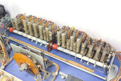 Motorized Trip Bank in standard position
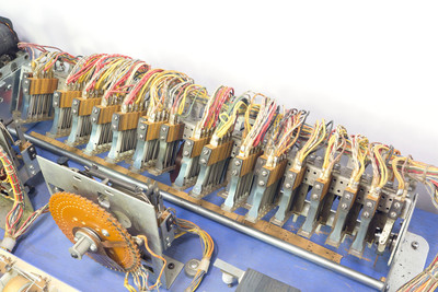 Motorized Trip Bank partially rotated
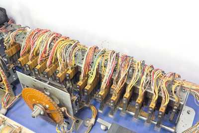 Motorized Trip Bank fully rotated
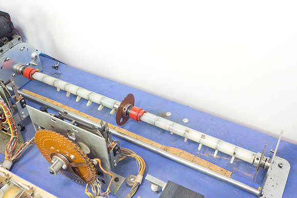 Motorized Trip Bank relays removed
Once the relay rack is removed the rotating shaft can be released by removing the end bracket. Then an E clip on the end of the shaft can be removed to release the reset cams and allow the replacements to be swapped in.
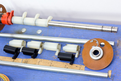 Reset cams to be replaced
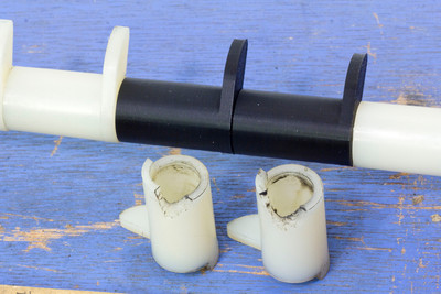 Replaced reset cams
The Clutch
Of the several Bally games with Motorized Trip Relays, On Beam is one of the few with the added complication of a clutch, two actually, shown here in detail.
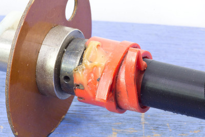 Clutch assembly
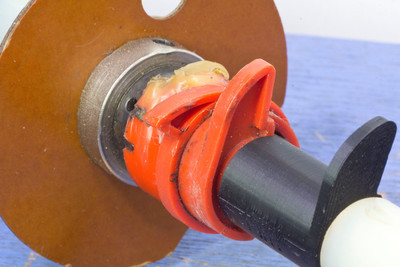 Clutch assembly
The purpose of the clutch is to allow either section of the relay bank to reset independently. On this game some of the trip relays can be reset while a ball is being played while others are only reset when the ball drains or at the start of a new game. The clutch is itself controlled by the first trip relay in the section. When that relay trips its armature drops and prevents one of the two clutch fingers from rotating. When the shaft rotates a spring hidden inside the clutch wraps tightly around the shaft and rotates the other clutch finger and all of the reset cams connected to it. If the controlling relay has not tripped, the clutch allows the shaft to rotate without engaging it or rotating its connected reset cams.
Both of the reset cams in this example appear to have been repaired at some point. Given their rarity and complexity I did not disassemble these clutches.
Final Results
The two videos below show the working reset mechanism in slow motion. The first video shows a complete reset of the trip relays where both clutches are engaged. The second video shows how one section of the bank can be reset when just one clutch is engaged.
Complete bank reset in slow motion
Partial bank reset in slow motion
Games with Motorized Trip Relays
Bally games with Motorized Trip Relays include:
- 1967 Rocket III
- 1968 Rock Makers
- 1969 Cosmos
- 1969 On Beam
- 1969 Joust
- 1969 King Tut
- 1970 Bowl-O
- 1970 King Rex
- 1970 Trail Drive
- 1972 El Toro
- 1973 Monte Carlo
- 1973 Odds & Evens
- 1973 Hi-Lo Ace
- 1974 Bon Voyage